Collapsible content
Magnetization Instructions
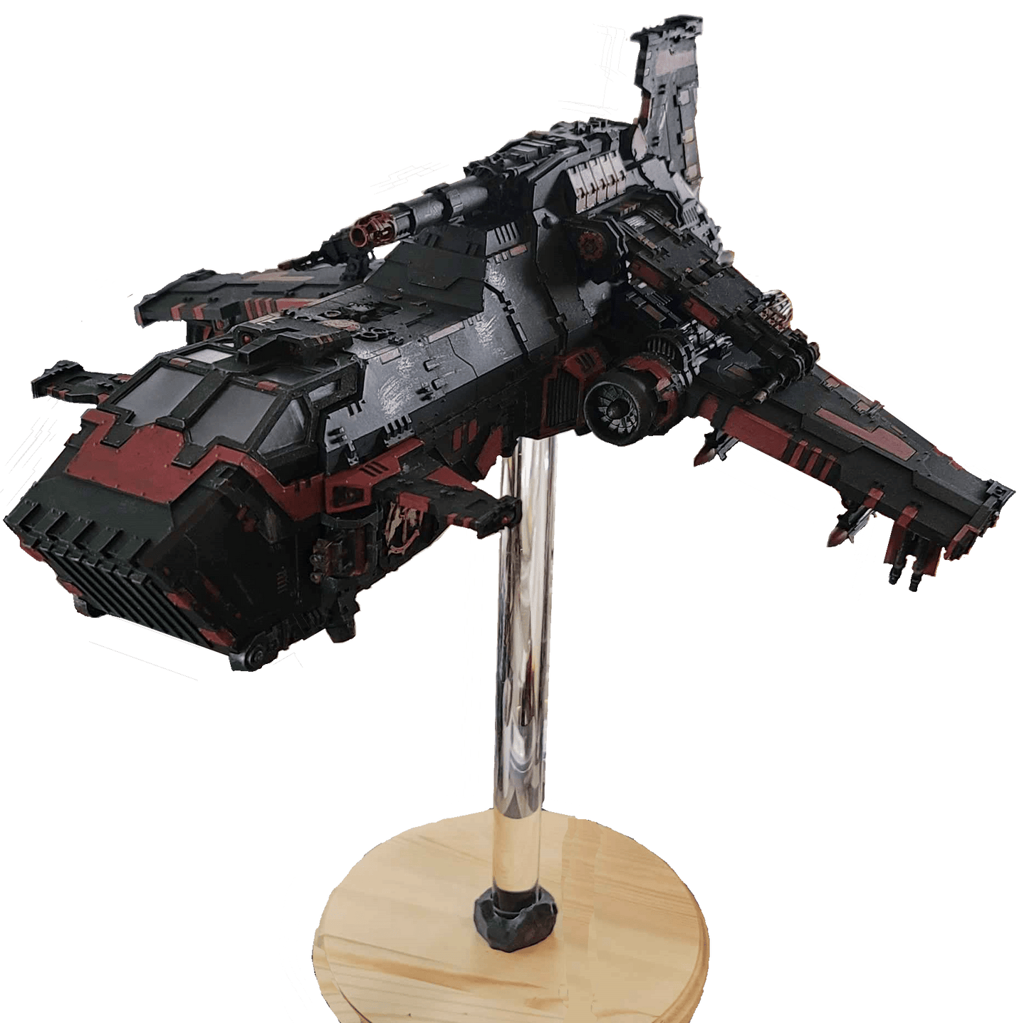
2024 Thunderhawk Magnetization Kit
Parts List
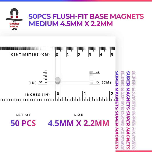
Magnets
Quantity
|
Diameter
|
Height
|
12
|
10mm
|
3mm
|
12
|
6mm
|
2mm
|
12
|
4mm
|
3mm
|
Quantity | Lenght | Width |
2 | 12mm | 11mm |
2 | 17mm | 11mm |
1 | 65mm | 7mm |
3 | 20mm | 7mm |
2 | 10mm | 7mm |
1 | 6mm | 7mm |
2 pcs 0.125” by 1.25” brass/steel rod (or metric equivalent)
Kit
MEGA Large THUNDERHAWK Flat Magnetic Flight Stand: 12" model
Descriptions
Methods:
Magnet Polarity:
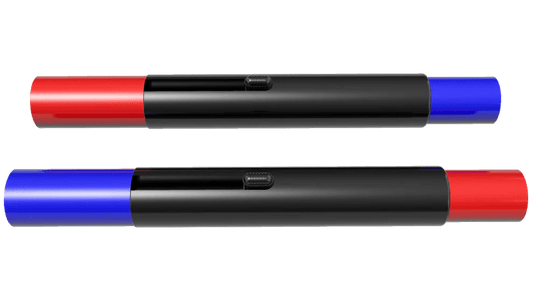
To keep track of the polarity of the magnets, we use a set of Magnicator tools. We may refer to the polarity of the magnets as “red” or “blue” after which magnicator is attracted to that magnet’s surface. (The normal terms such as North & South or positive & negative are unnecessary here.) If you do not have those or similar tools, ensure you have some other method of tracking a magnet’s polarity. For example, you might color one surface of a spare, large magnet with a marker and reference back to it every time you use a magnet. Possibly attach that large magnet to a tool that you can keep nearby but you won’t need to use; A hammer or wrench, for example.
We use a convention that all magnets in the fuselage of the plane are blue because Body = Blue. The wings always use red orientated magnets, because that’s where the guns are and Guns = Fire = Red. The magnets on the landing gear do not matter, as they are attracted to the metal sheet parts.
Drill Guides:
This project relies on drilling matching holes in two different parts of the model in order for the magnets to align. There are several methods that can be used to accomplish this.
- Careful measurements
- Carefully measure the area in which the holes will be drilled on part A.
- Mark locations such that the holes are distributed evenly over the area.
- Perform the same measurements on the mating area on part B.
- Drill the holes as described in the instructions.
- Double-sided tape
- Attach a piece of double-sided tape to part A, large enough to cover the entire area of where the magnets will be. Include a portion of tape that will stick out of the joint once both parts are joined, called the tab.
- Mark and then drill or poke small holes in the tape enough to mark the surface of part A. They do not have to be perfectly oriented, but try for a good distribution.
- Press part A and part B together in the configuration that the model will need to be in. Use a lot of force.
- Carefully remove part A from part B. Use the tab to ensure that the double-sided tape remains on part B.
- Mark and drill/poke small holes in part B.
- Drill the holes as described in the instructions.
- Hole Center Locators: A set of cylinders sized to fit tightly in commonly used hole diameters. There is a metal pin point at the center of the cylinder, used to transfer the location of the center of that hole to a mating part.
- Measure, mark, and drill the appropriate holes in part A using a small drill bit; 3mm or 1/8”.
- Insert the appropriately sized hole center locators (HCL) into the holes on part A.
- Press part A and part B together in the configuration that the model will need to be in. Use a lot of force, maybe hitting one of the parts with a small mallet.
- The pin points in the HCL should have transferred the locations of the holes to part B.
- Using the hole centers, drill the holes as described in the instructions.
Main Wings:
Each large wing uses 3 pcs 10mm x 3mm disk magnets and one metal rod and mates to the fuselage with 3 pcs 10mm x 3mm disk magnets and an accompanying hole. Repeat for the other side.
Thunderhawk Main Wing. Note the metal rod in between the two magnets.
Thunderhawk Fuselage, showing the magnets for both the Main Wing and the Attack Wing. Note the hole for the metal rod.
Attack Wing
Each attack wing uses 2 pcs 6mm x 2mm disk magnets. The mating fuselage also uses 2 pcs 6mm x 2mm disk magnets. Repeat for the other side.
Lascannon Attack Wing. Fuselage picture is shown in the Main Wing section above.
Canards
The front canards (small wings) each use 2 pcs 6mm x 2mm disk magnets. The mating fuselage has sheet metal cut into 12mm x 11mm rectangles and 17mm x 11mm rectangles. Repeat for the other side.
The Front Canard (small wings)
The sheet metal pieces for the front canard wings.
Tail
The tail uses 3 pcs 4mm x 3mm disk magnets. The mating fuselage has sheet metal cut into a 65mm x 7mm rectangle.
The magnets on the bottom of the Thunderhawk tail.
The sheet metal piece for the Thunderhawk tail.
Front Landing GearEach landing gear uses 3 pcs 4mm x 3mm disk magnets. The front landing gear has sheet metal cut into one 20mm x 7mm rectangle and one 7mm x 6mm rectangle.
The front landing gear for the Thunderhawk.
The sheet metal pieces for the Thunderhawk front landing gear. Feel free to wedge the metal sheets into the cavity in order to get the best gluing points.
Wing Landing Gear
Each landing gear uses 3 pcs 4mm x 3mm disk magnets. Each wing landing gear has sheet metal cut into one 10mm x 7mm rectangle and one 20mm x 7mm rectangle. Repeat for the other side.
Wing landing gear for the Thunderhawk.
The sheet metal pieces for the wing landing gear.
Flying Stand Kit
There are instructions on how to install the MEGA flying stand kit on the Magnet Baron website.
https://themagnetbaron.com/products/mega-large-flat-magnetic-flight-stand
The center of gravity on the new Thunderhawk model is located just in front of the wings.
Location of the 25mm by 3mm magnet for the Thunderhawk MEGA flying stand.
For the base, we used a wooden plaque purchased at a local craft store.
Mega Large Assembly Instructions
- A: Insert one disk magnet into the magnet alignment tool. Pay attention to polarity! We are again using "red up" polarity. Apply glue to the bottom of the acrylic rod. (See detail picture following.)
- B: Insert the acrylic rod into the magnet alignment tool and glue it to the magnet.
- C: Once the glue has set, remove the acrylic rod and disk magnet from the magnet alignment tool. You can use a pin, paper clip (shown), or other tool to help remove the pieces from the tool. There is a hole through the center of the tool to facilitate this.
- D: Rotate the acrylic rod & magnet such that the empty side is again facing the magnet alignment tool.
- E: Insert another disk magnet into the alignment tool and pay attention to polarity. Using "red up" polarity again allows you to use the rod & magnet assembly in either orientation.
- Perform steps A through C again.
Step 3: Turn your model over, and glue the fourth disk magnet to the middle of the model, approximately under the center of gravity. Pay attention to the polarity again! Using "red up" polarity here allows the model to be attracted to either end of the acrylic rod & magnet assembly.
Final: This is a completed flight stand magnetization kit. You can see how the care in tracking the magnet polarity has allowed the parts to come together. From the top to the bottom, the polarity of the four magnets are Blue-Red-Blue-Red to Red-Blue-Red-Blue.
Mega Largge Flight Stand Contents
Item |
Dimensions |
Assembled Height |
4": 114mm (4-9/16") 7": 189mm (7-9/16") 12": 314mm (12-9/16") |
Acrylic Rod (Undrilled) |
25mm (1") Diameter x 100mm (4”), 175mm (7”), 30mm (12”) |
4 Disc Magnets |
25mm x 3mm (1" x 1/8") |
1 Rock Anchors |
Mega Large (25mm) Inner Diameter |
1 Flight Stand Guide |
Mega Large |