
Venatari Magnetization Instructions
Full guide
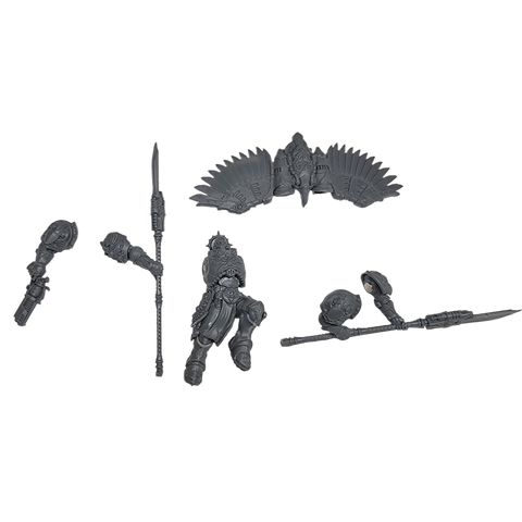
Drilling required: drill the loose torso from one armpit to the other with a 3 mm bit for 6pcs 3mm x 11.5mm Cylinder Magnets. Do not drill after assembly.
Don't have the kit yet? Get the Venatari Custom Magnetization Kit here.
Venatari Magnetization Instructions
| Step | Description |
|---|---|
| Step 1 | The Jump Pack |
| Step 2 | The Body |
| Step 3 | The Arms & Shoulder Pads |
This article explains how to magnetize the Venatari model using the kit from The Magnet Baron. You will be able to use the end model with a Verutum Destroyer pole arm, a Tarsus Buckler and Kinetic Destroyer, or a Neutronium Cascade Mine in place of one arm.
The length of these instructions may seem intimidating, but they were designed to make sure you see everything from every angle and do not make a mistake.
To assemble this kit you will need thick or gel super glue (such as Maxi-Cure Plus; never thin CA glue), files or sandpaper, and a knife or clippers, plus any drill bits and pin vise listed in "For this guide you will need." Do any drilling or cutting on the loose part before you assemble it. Please follow the normal assembly instructions that come with the plastic kit; the steps below cover only the magnetization.
To keep track of magnet polarity we use a set of Magnicator tools. We refer to a magnet's polarity as "red" or "blue," after the Magnicator end that is attracted to that magnet's surface. If you do not have those tools, use another method to track polarity, for example mark one face of a large spare magnet and reference it every time you place a magnet.
For this guide you will need
- Thick or gel super glue
- Magnicators V2
- Drill Bit Small Metric Bundle 1mm-3mm
- Needle Files
- Files or sandpaper, knife or clippers
The complete kit includes 6pcs 3mm x 11.5mm Cylinder Magnets, 24pcs 3mm x 0.5mm Disc Magnets, and 24pcs 3mm x 2mm Disc Magnets, along with the Extra Small flight stand parts: six Short acrylic stems, six printed rock anchors, and one flight-stand guide.
| Diameter | Thickness | # |
|---|---|---|
| 3mm | 11.5mm | 6pcs |
| 3mm | 0.5mm | 24pcs |
| 3mm | 2mm | 24pcs |
| Total | 54pcs | |
| Code | Name | Magnet | # | Sprue | Kit |
|---|---|---|---|---|---|
| Venatari Hex Cap Top | 3mm x 2mm Disc | 6 | Venatari Jump Sprue | Venatari | |
| Venatari Hex Cap Bottom | 3mm x 2mm Disc | 6 | Venatari Jump Sprue | Venatari | |
| Extra Small rock anchor | 3mm x 2mm Disc | 6 | Flight stand | Venatari | |
| Extra Small flight-stand guide | 3mm x 2mm Disc | 1 | Flight stand | Venatari |
Mark the recessed printed-part identifiers after support removal if that helps keep the parts organized.
Step 1 The Jump Pack
Magnets Used
| Size | # | Where |
|---|---|---|
| 3mm x 2mm Disc Magnets | 12pcs | Six Venatari Hex Cap Top pieces and six Venatari Hex Cap Bottom pieces |
| 3mm x 2mm Disc Magnets | 12pcs | Two per supplied Extra Small rock anchor |
3D Printed Parts
| Code | # |
|---|---|
| Venatari Hex Cap Top | 6 |
| Venatari Hex Cap Bottom | 6 |
| Extra Small rock anchor | 6 |
| Extra Small flight-stand guide | 1 |
The Extra Small flight-stand guide centers the rod-to-rock disc magnets during assembly.
Model Parts
| Part | Use |
|---|---|
| Jump harness parts 64 and 65 | Interior matched by the Hex Cap Top |
| Plastic part 66 | Replaced by the Venatari Hex Cap Top in plastic-kit step 1B |
| Extra Small Flat acrylic flight-stand stem | Six Short stems are supplied in this complete kit |
Two Venatari Jump sprues hold the printed hex-cap pieces. Clip supports from the base before removing them from the parts, then sand and file as needed. Install magnets in the hex-cap pieces before proceeding, starting with the Hex Cap Bottom. Use another magnet to seat the first magnet fully and check polarity as you work.
In plastic-kit step 1B, the Venatari Hex Cap Top replaces plastic part 66. It matches the interior details of jump harness parts 64 and 65. Glue a supplied Extra Small Flat acrylic flight-stand stem (Short) into the Venatari Hex Cap Bottom. Glue the supplied printed rock anchor to the other end of the stem, then use two supplied 3mm x 2mm Disc Magnets per stand for the rod-to-rock connection.


Step 2 The Body
Magnets Used
| Size | # | Where |
|---|---|---|
| 3mm x 11.5mm Cylinder Magnets | 6pcs | One loose torso per model, drilled armpit to armpit |
3D Printed Parts
| Code | # |
|---|---|
| None | 0 |
Model Parts
| Part | Use |
|---|---|
| Torso | Drill from one armpit to the other before assembly |
The torso and arms use the same method as the Custodian Guard magnetization guide. Drill and insert a 3mm x 11.5mm Cylinder Magnet into each loose torso from one armpit to the other. Use the red Magnicator on the left side of the torso for consistent polarity.


Step 3 The Arms & Shoulder Pads
Magnets Used
| Size | # | Where |
|---|---|---|
| 3mm x 0.5mm Disc Magnets | 24pcs | Weapon-option arms |
3D Printed Parts
| Code | # |
|---|---|
| None | 0 |
Model Parts
| Part | Use |
|---|---|
| Weapon-option arms | Verutum Destroyer pole arm, Tarsus Buckler, Kinetic Destroyer, and Neutronium Cascade Mine |
| Shoulder pads | Glue directly to the magnetized arms |
Glue the arm magnets inside each arm and make their polarity compatible with the torso. The source guide specifies the blue Magnicator on left arms and red on right arms. Each model can use a Verutum Destroyer pole arm with two arms, or a Tarsus Buckler and Kinetic Destroyer with one arm each. A Neutronium Cascade Mine can replace one arm. Do not magnetize the shoulder pads because the plastic kit supplies enough to glue directly to the magnetized arms.


Conclusion
Continue to assemble the rest of the model as per the printed instruction book.
Full guide